From playful forms to mathematical structure
Four detailed opening studies built from surfaces, fields, and a sectioned mechanism.
The next color pass brings the shared inks into these detailed models. The images below preserve this engineering round.
The previous round was too playful. Large blocks of saturated color and a few simple objects suggested toys. For a publishing toolkit aimed at inventors and researchers, the opening should invite closer inspection.
The revised comparison uses four specific subjects: a minimal surface, a periodic nodal surface, an ideal dipole field, and a planetary reduction stage. Silver and graphite carry their shape. The existing cobalt, cyan, and ochre inks identify coordinates, sections, and construction witnesses. Those ink colors remain identical on both boards.
Enneper: curvature and coordinates
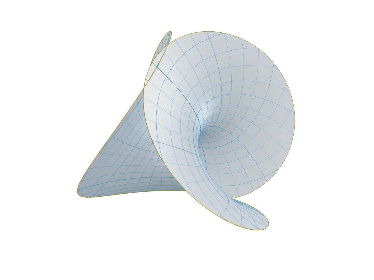
This is a sampled Enneper immersion, with 71,456 triangles and a conformal coordinate net. Its analytical parametrization is
The model samples the disk and applies a uniform display scale. The smooth mathematical surface has zero mean curvature; the rendered triangle mesh approximates it. The blue curves follow constant parameter values, and the ochre curve marks the disk boundary. This is an immersion that can intersect itself, not a fabricated sheet with thickness. Wolfram MathWorld gives the parametrization and curvature.
Gyroid: expose the interior
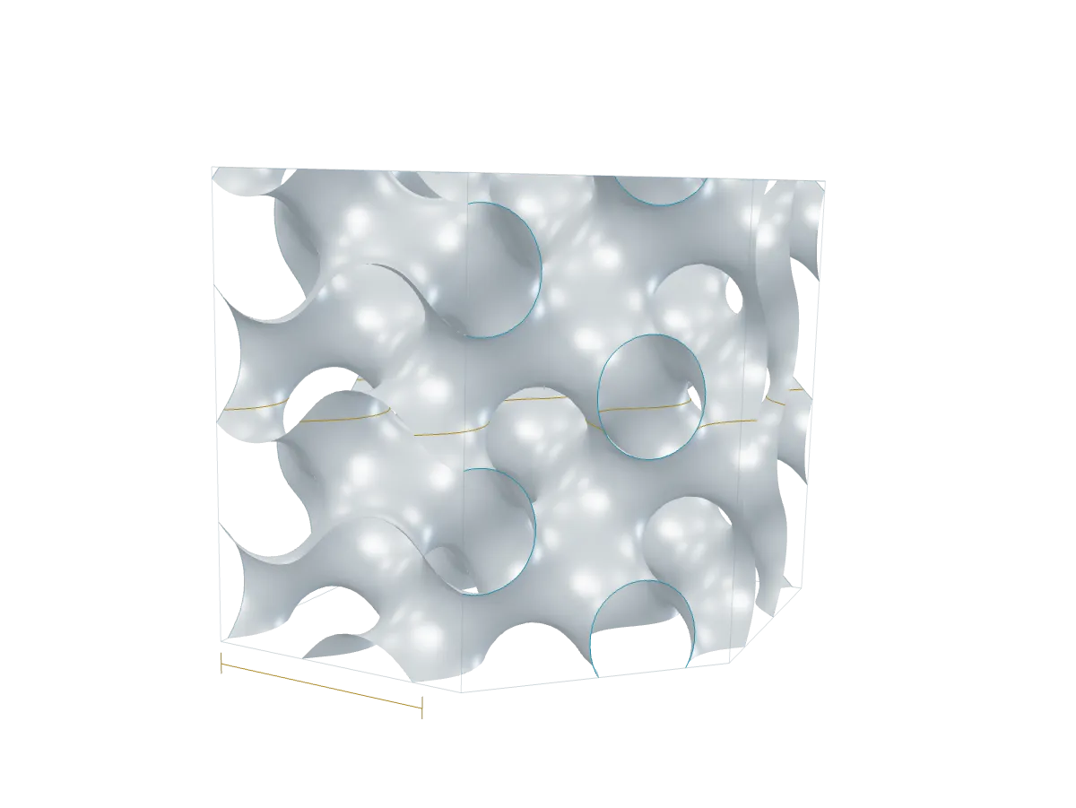
The implicit field is
We extract with indexed marching tetrahedra on a grid, then remove an oblique corner to reveal the channels. A finite specimen covers multiple periods; a dimension witness marks one period. Cyan traces the cut and ochre marks a central section. Analytical gradient normals keep the 98,926-triangle mesh visually smooth across irregular triangles.
This trigonometric construction is a nodal approximation, not the exact minimal gyroid. The distinction matters: the approximation is convenient to sample, but does not inherit every property of the exact surface. The field formulation is described in the computational gyroid design paper; MathWorld describes the exact gyroid.
Dipole: many lines, one rule
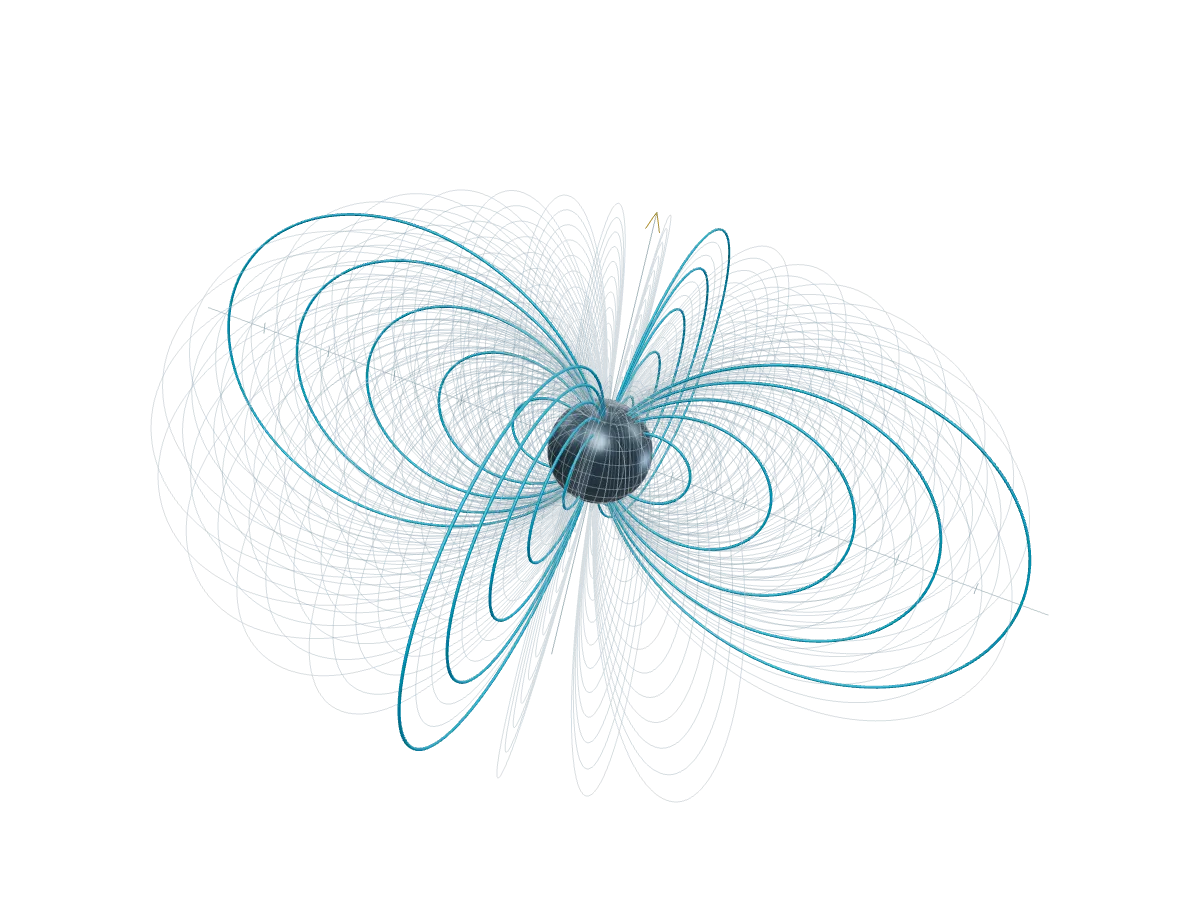
Instead of arbitrary flowing curves, every field-line family follows
Here is measured from the dipole axis and is the equatorial crossing radius. Thirteen shell families, sampled at multiple azimuths, produce the layered structure. Selected meridians have thin tubes for depth; the remaining curves use fine transparent lines. A missing azimuth wedge exposes the inner families. MIT’s electrodynamics notes derive this field-line equation in section 7.4.
The coordinates are dimensionless. A reference sphere of radius 0.34 excludes the singular origin; it is not a physical magnet model. Line spacing, tube thickness, and the removed wedge are display choices. This is an analytical illustration, not measured field data or a numerical solver.
Reduction: parts with a purpose
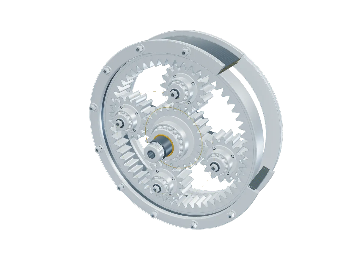
A 24-tooth sun, four 16-tooth planets, and a 56-tooth internal ring share one module and 25-degree involute flanks. The counts satisfy
These are the center-distance and equal-spacing conditions listed in KHK’s planetary gear guidance, page 2. With the ring fixed, the ideal sun-to-carrier reduction is .
The 123,548-triangle illustration includes a sectioned housing, carrier webs, 56 bearing balls, stepped and splined shafts, socket heads, and section hatching. It moves as one rigid view; the gears do not simulate transmission dynamics. Tooth roots use radial connectors below the base circle, rather than cutter-generated trochoids. Axial spacing is illustrative, with no manufacturing tolerances. It is a parametric engineering illustration, not production CAD.
Make the detail inspectable
The renderer fits actual vertices into the opening; fitting rotated bounding boxes had left too much empty space around curved objects. Annotation anchors are projected from the same object coordinates as the mesh, while their labels stay in the margins. Small zoom buttons reveal detail without capturing the page’s scroll wheel. Drag, arrow keys, zoom, and Reset pause the subtle motion.
A room lighting environment, physically based materials, and restrained directional lights reveal curvature. The grid is a visual alignment aid; dimensions come from the labeled geometry. The equation beneath each object remains ordinary accessible KaTeX content.
The comparison loads stills. Only an opened, visible study starts its graphics engine. Motion remains capped at 30 painted frames per second, stops outside the viewport, and starts paused when reduced motion is preferred. Missing graphics support leaves a contour poster and an explanation.
All four images in this article are captured from the browser renderer at the resting pose. docs/art/capture-engineering-forms.cjs records the 1200×900 capture recipe. The earlier article retains its original images, so the development history stays legible.
These remain site-owned Labs proposals. The geometry modules, renderer, and styles live in the demo; the approved homepage and shared component API have not changed. The customization guide identifies what to edit.